|
PartMaster Milling is a system designed to create complete prgrammes for
NC and CNC milling machines and machining centres. PartMaster Milling is
completely icon driven with easy to understand dialogs to input all
programme information - no programming language needs to be learned, all
required geometry can be automatically extracted from a PartMaster CAD
drawing or read directly from a DXF file. PartMaster Milling is ideal for
those new to CNC machining, whilst offering many advanced features for the
experience user.
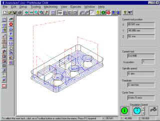
Programme verification is made easy by fast, clean toolpath display in
top, side, front or isometric views
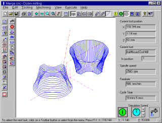
Example of the Merge command to create a
ruled surface between 2 contours at different Z heights
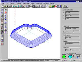
Example of Z-Profile for shapes with non
vertical sides
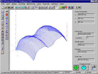
Example of surface patch defined by two
profiles
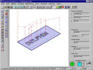
Example of raised lettering |
- Support for 2,
2.5 and 3 axis milling and rotary axes A and B.
- Tooling database.
- Display of
component and toolpath in Plan, Side and front Elevations and Isometric
Views.
- Display tool
centre-line, tool path envelope or full tool animation.
- Canned cycles for
milling, drilling, drilling, peck-drilling, deep-hole drilling, reaming,
boring, tapping and pocketing.
- Subroutines.
- Simplified 2D
contouring control with automatic generation of lead-in and run-off.
- Z axis profiling
which allows machining in the ZX & ZY planes.
- Tool offsetting
for ball-nose and square ended tools.
- Merge top and
bottom 2D contours to produce and machine aruled surface (square ended
tools).
- Automatic area
clearance of any contour with up to nine islands, with many machining
options.
- Engraving
facility that allows any text to be machined, with size, angle and
mirror image options, also radial text.
- Ramping with arc,
straight line or zig-zag approach
- Machining of
surface patches defined by two profiles.
- Ruled surfaces
defined by profile along line or turned around point
- Cycle time
estimates.
- Output to
virtually any machine tool controller, with the built-in post processor.
- Operator set-up
sheets which show tooling required and machining sequence.
Choose
from over 50 Post Processors including Fanuc, Heidenhain, Siemens, Rambo,
Hurco etc.
The end result ? reliable machine code that you can trust without
having to edit by hand |