PARTMASTER 2D CAD MODULE - FEATURES

Next   Back

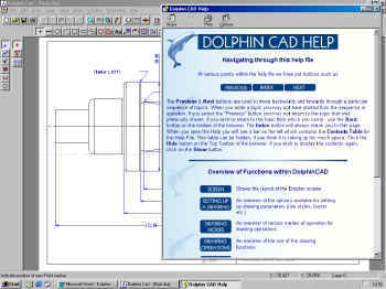
PartMaster CAD is a general purpose 2D draughting system aimed at mechanical engineering. It can be used to prepare engineering drawings or to create geometry which can be used in the machining modules within the PARTMASTER system. It is icon driven with full menus and a powerful built in help facility.

PartMaster CAD is easy to use and quick to learn. It has been designed for engineers that may not be familiar with CAD systems.

DCAD has a powerful WSIWYG preview function so the selection of the correct elements for fillets, chamfers, tangent circles etc. is extremely simple with one-hit execution


New help system

Direct contour export to CAM

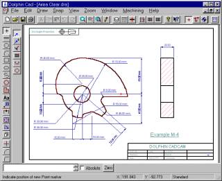
DCad is ideal for producing complex drawings as well as simple geometry. If you don't need to produce full working drawings you can use DCAD to draw just the contours required for machining. These contours will be automatically transfered to the Cam system as required.

Many sub-contract companies are being supplied with the drawings on disk in the DXF format. DCAD allows you to read-in these drawings and then select just the parts which need to be machined. The process is straightforward and can save a lot of time.

Standard "masters" can be created and included into any drawing as well as company logos etc.

  • Drawing primitives include Point, Line Circle, Arc, Elipse, Polygon, Symbol, Text, Dimension, Hatch & Notes.
  • 5 snap modes, Near, Finite, Orthographic, Middle and Grid.
  • 11 Linestyles and 17 Hatch patterns - most of which can be redefined by the user. Lines can be drawn to any thickness with rounded or square ends and can also be "hollow".
  • 255 layers. Layers can visible or invisible.
  • Automatic parameter assignment e.g. selecting LINE can automatically set line width and style, pen number and drawing layer.
  • Construction facilities include tangent lines, arcs and circles, parallel lines and arcs.
  • Curve fitting function creates smooth or discontinuous curves ans splines through sets of points.
  • Semi-automatic hatching with area, moment and perimeter calculations.
  • Automatic dimensioning in inch/metric or both. Dimensions may be Horizontal/Vertical, Parallel, Radial, Circular, Angular or Leader imperial/metric or user defined units.
  • Standard and italic text with a choice of technical and True-Type fonts, also user definable. Text can be left, right or center justified, or fitted between two points. Ascii text can be incorporated from an external application such as a word processor.
  • Editing functions include Trim, Extend, Intersect, Fillet, Chamfer, Delete, Repeat, Copy, Mirror image.
  • Output to standard plotters, as well as direct output to your normal office printer.
  • Powerful new help system.
  • Data exchange with other CAD systems via DXF format.